Monday, December 22, 2014

Fletcher Demolition Progress


Hi Sam, 
Hope you're enjoying the xmas break. Just wanted to share these photos of Fletcher low rise and Fletcher Tower with you. You can see that in the low rise now they are well on their way with the demolition of it and you can really see the skeletal frame of the building. 

I hope to have a similar structure in my building too as I discussed with you in our last tutorial (May have to double up the RHS columns in the workshop spaces in order to make them work). 


I'm currently working on an environmental strategy for the building, I want to make use of the river alongside the site but as it's stagnant it's proving difficult so I think i need to look at other methods. In my tutorial with Rob Atherton, he mentioned I'd need mechanical ventilation in the workshops for the extraction etc. 

Anyway, just wanted to share these photos with you.

Have a nice Christmas! 

Veena :) 

Monday, December 8, 2014

Workshop 2 Thoughts

Hi Sam,

Just thought I would make a quick post to review the feedback I received from the workshop. Looking at my review sheet and my own recollection the key questions raised were:

  1. The tower element was not visually designed.
  2. The hangar element was not visually designed.
  3. Issues relating to the large elements (tower/hangar) in terms bulk and scale of in the context of a planning application, Tom also mentioned the issue of infrastructure briefly.
  4. Key sections through hangar an tower missing.
  5. The pod loading system was questioned, is it quicker? is it necessary? although I think that this was resolved when I finally got round to talking through the arrivals terminal. 
  6. How do the airships anchor to the building.
I'll comment on these now and attempt to address some of these for our meeting on Thursday, but for now to get the ball rolling

1,2,3 and 4
For the review I focused on the layout of my terminal rather than the tower and hangar elements, I suppose that I had been making sure I tried to get the bread and butter of this project functioning correctly before I started the hangar, tower and mechanical elements of the project. Although I had massed them out in model form and worked out the circulation of pods/ airship hangar entry etc. the form itself was not resolved at all.

Tom mentioned bulk and scale as an issue in the review, would it be fair to argue that because the nature of the project as one of the flagship terminals for a worldwide network that some leeway would be afforded on the bulk an scale of the project? This is the kind of exceptional project that would be given this kind of leeway for both its social and economic benefits it brings to the local area.

Finally Tom also mentioned the infrastructural issues this is something which I highlighted in my Town Plan, which highlighted both the connection of Farnborough to existing transport infrastructure as well as the flight path of incoming and outgoing aircraft at the existing aerodrome.

Site Plan, highlighting the local transport infrastructure.


5&6
I feel that the design of the pods and the mechanism by which they are circulated through both the hangar and the tower is the next step in the design of the project, I have avoided getting bogged down in the specifics of the mechanism up until now however I think that this is the element of the architecture which will give the project it's theater, with visible circulation of the pods and docking and disembarking of the airships.


Review 2 Board Layout
I have looked at the requirements for Review 2 and they say:

"APART FROM THE REPORT AND CD, THERE ARE NO REQUIRED OUTPUTS FOR REVIEW 2. STUDENTS CAN
PRESENT WHATEVER THEY WISH.
The outputs listed are suggested only, although some of them may be necessary for a successful outcome at Review 3.
They are therefore shown in grey text."

They are:

"recommended drawings
• A complete set of plans, elevations, and sections. At least the ground floor plan, one of the sections, and one of the
elevations, should be at 1:200. All drawings should show the relationship of the project to its immediate context.
• A location plan or location model, showing the surrounding context and the new building itself.
• At least two 3D views of the project (one internal and one external) depicting the life of the building, in its context
recommended models
(in addition to any location model as mentioned above): a model or models of the building, to any scale. Models must be
placed where the jury can see them. This model will be the most important item you present."

From this I have drawn up a board layout and I am currently working through some ideas in my head for the digital presentation which was beyond poor in the previous review, however i intend to utilise GIFs and use it to go through areas of my terminal at a larger scale. I think this is important to nail down early due to the large nature of my project fitting it all on the board in a cohesive manner is a challenge.


2 Projects I Aspire To
Just as a quick addition I though I would include some images from a couple of projects which I aspire for my own to resemble. Just to give you and idea of where I want to head, with large 3D's to give the overview, then breaking the project down into drawings of its individual parts.

Slow Fish Market


Frackpool


This week I just aim to finish my site model, sketch some proposals for the tower/ hangar elements, produce an outline proposal for the tower/pod mechanism and possibly begin modelling it.


Thanks,
Andrew


As an appendix I though I would attach some pages from my review:
Site Plan


Departures, arrivals and baggage circulation.

Section through departures terminal,
highlighting environmental approach.


Saturday, November 29, 2014

Tutorial 27/11

Hi Sam,

Apologies for not attending my tutorial on Thursday, I wasn't going to come in at all until I saw Tom's e-mail regarding technical tutorials and I felt no matter how ill I was I couldn't miss one of only two environmental tutorials we have this year, so I just bit the bullet and came in and then went straight home.


   Massing

First thing, I finished off my massing diagram sheet:

Massing Diagram of Initial Proposal


This is a three dimensional representation of my initial massing sketches which have developed from my feasibility, this has then been exploded to show each individual element of the design and its approximate size in sqm at this stage, which has been tweaked based upon the typical numbers calculated. In the bottom right is an un-exploded model which showing the massed proposal as a whole, showing how the departures terminal, docking tower and arrivals terminal wrap around the south east corner of the hangar.


  Layout

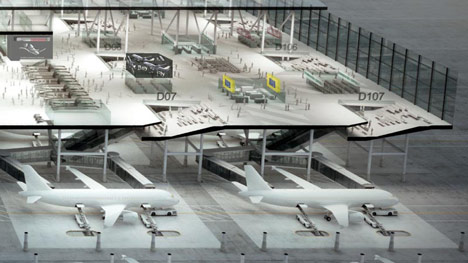
Based upon the massing diagrams above, I have began to work on breaking up these spaces at 1:200 on my wall. The design works on the principles of a linear transport terminal up until boarding. At this point it works on a similar principle to the 'Drive Through Airport' by Burro Design, whereby detachable pods circulate up the tower from the departures terminal to the docked airship. Simultaneously the arrivals pod is unloaded and circulated down the tower to the arrivals terminal where passengers disembark and baggage is unloaded. From there the pod is circulated to the  hangar, where maintenance/ re stocking/ other apron services occur.

********IMAGE OF 1:200 PLAN WITH SKETCHES UP ON THE WALL********

At the stage where I felt the space had been broken down enough I took this into CAD and have continued to work upon the specifics of the layout using both sketching at 1:200 and CAD in tandem. Once I am happy with the solution I move onto the stage of the linear approach to processing the passengers.

CAD plan in development, the 'Check-in' area (bottom left) has been developed
further than the 'Waiting and Retail' area (bottom right)


One precedent I have been thinking about a lot at the moment is the Eurostar terminal at St Pancras, which from my recollection is a very simple, pleasant and efficient terminal in my experience; which from what I can see should have the capacity to deal with a similar but higher passenger count than my proposed Airship Terminal (Airship Terminal = 12,500, Eurostar = approx 30 trains a day with 600 passengers makes a max load of 18,000 passengers a day.) I suppose although it is not particularly architecturally outstanding, my experience of the efficiency and ease of travel is something I am keen to emulate, this may be down the extremely short travel distances involved and similar to my idea for the pods has one combined 'Gate Lounge' for all of the platforms.


  Circulation Diagrams

************************ W.I.P***********************


  Site Model

This week I have also fully cut a site model which is at 1:2000 @A2 which is currently in a state of assembly, I hope to use this to display a massing model of my proposal and perhaps one further model which highlights the materiality of the different building components.


1p for scale


  Structural Strategies

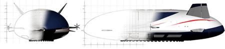
Although I have not had my structural strategies tutorial yet I do have an overall idea for what should inform the material and overall structural strategies.  I see this terminal as a kind of flagship project which along with a select few other terminals and retro fitted docking stations would provide the airship with a springboard to become a staple part of the 21st century. With this in mind the building should reflect this, I envisage a kind of airship inspired high-tech. This would make the whole project  in program, aesthetic and its engagement with the process through the airship hangar a true celebration of the airship as a mode of transport. With the addition of the nature of embarking and disembarking proposing a method in which the airship can be brought up to date and begin to meet today's demands of a mode of transport.

This 'Airship Inspired High-Tech' would consist of a combination of lightweight frames, translucent skins and tension wires. But all this lightweight structure would need to be grounded into the site by some heavier architectural elements, perhaps the service spines?


  Environmental Strategies

As mentioned I had my 'Environmental Strategies' tutorial with Rob Atherton yesterday, we spoke about how the hangar would form a part of my ventilation strategy used as an outlet for cross ventilation as it is a sheltered but otherwise unconditioned space. We also looked at the potential use of the service spines as tool for a night cooling strategy if constructed out of masonry, which was my initial notion, based upon the aesthetics mentioned earlier.

We also talked about solar strategies but he seemed happy with the way the current design was progressing naturally with regards to this, with the overhanging roof and stepped nature of the southern facade. Rob also mentioned that the arrivals terminal may suffer from low sunlight in the morning as it is facing east, an although that is not too much of a problem it may be something worth taking into consideration in future.


  Board Layout

With all of the above in mind I have created a board layout which I will try my best to produce for next week.


Couple of notes: the two 1:200 plans are one plan of the whole building at terminal level perhaps with the ground level kerbside elements on tracing paper to place over the top? The environmental and structural precedent pages would provide simple sections of key parts of the building with the relevant structural and environmental strategies noted upon them.


I think that's it.

Andrew

Saturday, November 22, 2014

FOR TOM

Tom, thank you for uploading and sharing your work in progress on the dropbox folder. Looks like the (Review 1 stage) 3D CAD site model and High Street Facade drawings are now well advanced.

You have also produced plans of a school building, which in some ways look quite advanced - you have loos, stairs that work, classrooms with windows, etc etc, but there is a disconnect between the midi-micro and the macro.  I say midi-micro because although windows are drawn, there is no indication of the qualities of these, or of the staircase, or the corridors. At this stage, it's important to work at all scales and sensory levels - ie - from how does this space make you feel, to how it operates as part of a school metabolism, to how this new building helps the town around it work better architecturally, socially, politically. This is a contribution to a High Street. It IS a High Street, or is it?

I think you need to step back a little from the midi-micro and ask yourself some bigger questions, and I encourage you not to work in CAD which is

a) reductive
b) scaleless
c) abstract.

I encourage you to get on your coat and leggings and pitch a tent on the site and sit there drawing in a sketchbook, thinking, looking. Is this the best building for the town? Remember only around 1% of the townsfolk will ever pass through its doors. The other 99% have to live with the consequences of your actions, without directly benefitting from the classrooms, etc.

I encourage you to make the building and its facilities more integrated with the fabric of the town.

Sam

Wednesday, November 12, 2014

Airship Design: Thunderbirds Are Go!

Hi Sam,

I though put this out there before we meet on Thursday.

 I was a little stuck on my layout, I wanted to begin the tower this week but I was really struggling with all the separation of different passenger types/ baggage/ apron services etc. After a day of stalling and not getting anywhere I decided to spend a little time working on the structure just so I was doing something at least (even though you said not to work in so much detail.) I also spent time looking at further precedents, both real and speculative, in Airport and Airship design so when I returned to my terminal it would be with a different perspective.


-Structure-

For the structure I took precedent from the airship hangar close to the site, modifying the model I had produced of the hangar to fit a grid for my initial plan, which is constructed on similar principles to the frame of an airship hull. The line work below is one module based upon the principles of this structure which can then be repeated.

Grade II listed  airship hangar adjacent to the site


One module of my own steel structure.

An image of the inside of an airship hull, showing
the void between the helium bags and the hull. Initially
 looked at as roof inspiration but will come back in a bit later.

Towards the end of this, I don't know why but I began to get preoccupied with what drawing style my project was going to take on so I spent a small amount of time producing the image below, using a combination of the quick steel structure and the initial Sketchup model I have been working on whilst working through my ideas.


Steel frame quickly applied to my model with line work and shadows exported to create a quick stylised render.


-Precedents-

Although I have a couple of reference books on Airport design and have initially decided to plan my Airport in a linear method I decided further precedents were needed, below are which have tweaked my thinking behind my layout.

The first precedent which really struck me was Drive Through Airport by Buro Fur Mehr. This totally changes the gate system, reducing the amount of passenger circulation by moving the aircraft instead. This got me thinking about my tower circulation in new ways which weren't just the reconfiguration of the plan which you can find in the books that I have found on airport design.

Drive Through Airport Diagram by Buro Fur Mehr 
http://www.dezeen.com/2012/06/23/drive-through-airport-by-buro-fur-mehr/

Drive Through Airport Render by Buro Fur Mehr 
http://www.dezeen.com/2012/06/23/drive-through-airport-by-buro-fur-mehr/


The second precedent of note was the  I looked at was the Aeroscraft ML866. Although not particularly inspiring imagery the principle of one hull being used for multiple uses was one which intrigued me and something I had been struggling with in terms of my brief with the different users of the airships commuters, sleepers, economy, cruise etc. This would be impossible to achieve with one hull.

Aeroscraft ML866

These are just the highlights, I have produced a little A4 PDF with all the precedents I looked at this week.


-Thunderbirds Are Go!-

So based upon the precedents previously, I began to think about how I could innovate airship design. As I mentioned last week the current teardrop shape fulfills all the necessary requirements, changing the aerodynamics of an airship would be a largely cosmetic change with no real substance/reasoning behind it other than affecting the image of airship travel, which may be something that is needed?

As I was stuck on tower element due the to amount of separation and circulation required, I wondered if this was something that could be solved by the design of the airship itself. Back to this image:

An image of the inside of an airship hull, showing
the void between the helium bags and the hull.
This is the space below the helium bags in a rigid airship which is where all the accommodation services etc. are located.  When there is nothing filling this void it is still there to maintain the aerodynamic properties of the teardrop shape. This got me thinking what if this part of the hull was interchangeable? Creating the main hull which provides the propulsion/buoyancy onto which a different pods could then be attached.

The best way I can describe this is using Thunderbird 2, which has different pods equipped for different needs, in a similar way to which my airship design would.


Full video of the Thunderbird 2 launch sequence.
 (more for fun than anything else relevant part is at 00:24)


-Tower Structure-

Taking this pod system and applying the principles of the Drive Through Airport, where by the pods are detached could then resolve my issues with my tower planning issues, as well as making for a rapid airship turnaround. Below is a slightly picture of diagram on my wall in my room.

Diagram highlighting the location of the pods and circulation within the tower.

Basically I envisage that an airship would dock and the pod would be removed, then it would be serviced and passengers disembark while the next pod complete with passengers baggage gets fixed to the main hull. Hope this makes sense,

-Other News-

I have started a 1:200 Site Plan on the wall of my room for when I start getting down to that scale, infact every wall of my room seems to becoming engulfed by this project.


I have been writing this post on and off since Monday but I will attempt to have more tower stuff by tomorrow.

Thanks,
Andrew

Monday, November 3, 2014

To Veena

Nice Veena, Good Digging! I realised that Rob Sheen in the Hub will have lots of photos of the interior of fletcher from all those exhibitions. You may be able to extract from the hub website / fb page.

Another source will be the architect Alan Short. I think they did the refurb of that building at the same time as the Queens Building. He was Dean at the time, I believe. Estates will also have copies of these drawings. They will be very detailed!

s.

Waste Development Framework for Leicester

Hi Sam,

I have found this document highlighting Leicester's strategy for the development of waste materials on the Leicester council website. They go into how planning applications will eventually have to be made with this strategy in place - you would have to show how any materials from demolition would be reused or recycled etc. (see the link to the dropbox below).

https://www.dropbox.com/home/LSA%205th%202014/Veena/141103

I thought it was quite interesting and a good foundation for me to build my argument of recycling materials. I have also emailed the construction company who are working on the Fletcher buildings so hopefully I will have some more information on the materials available to use!

Also, I went to a restaurant this weekend called Caravan... not sure if you've been there.. but they have used recycled furniture from offices and schools for the interior, old desks, chairs, stools from science labs etc.


Thanks,

Veena :)